In underwater photography, bringing your own light is essential. Water cuts down on transmission of red light, so the deeper you go, the more blue-green the scenery becomes. Because of the phenomenon of color constancy, you don’t necessarily notice this while you are diving. But as soon as you try to take photos, you find they all come out looking characteristically … marine. You might think you can fix it by adjusting color balance, but this only works for photos shot in the top 20 feet of the water or so. Deeper than that, the ability to fix in post-processing is limited. The data for red pixels simply isn’t there.
Knowing I needed a light for photography, I first got a video light and tried to use that for stills. In the end I found this useful as a focus light and for night illumination, but it did not provide enough photons for high resolution photos, especially on close-up and macro shots where you don’t want to shoot with the aperture wide open (as it makes depth of field too shallow). Strobes are the standard solution for this.
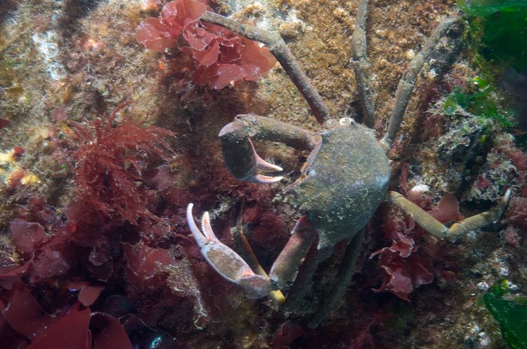
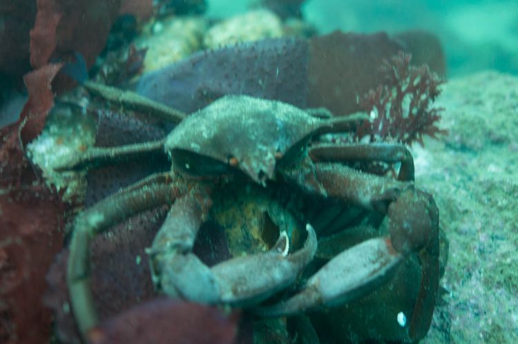
Photos with and without strobe
The problem
I have the Sony NEX-5N camera with the Nauticam underwater housing, and I came into possession of two used Inon Z-220 strobes (discontinued in 2005). I connected the strobes to the camera housing with fiber optic cables to use them as optical slaves, which means, when my camera’s main flash fired, the slave stobes’ built-in sensors would detect this through the fiber and they would fire at the same time. These days, optical sync is preferred over electronic sync cables, even though the Inons support both, because electronic sync cables are expensive and they are another thing that can flood. But the trouble with the optical slave connection between these devices, I discovered, is that the NEX-5N pre-flash can’t be turned off, and the Z-220s (unlike their successors, the Z-240s) do not support pre-flash with optical sync. This means that the strobes fire too early, on the pre-flash, and if they’re set to full brightness they can’t reload their capacitors fast enough to fire again on the main exposure. More modern strobes can detect this condition and ignore the pre-flash.
I looked into solutions for this, and found a product that might work: the Inon Focus Light Controller, which apparently plugs into the electrical port on the back of the strobe and provides an optical sensor that ignores preflash. But it did not seem rational to spend $400+ on a pair of these, especially since it wasn’t clear they would work.
With some more research, I found that hot-shoe adapters for the NEX-5 also suppress pre-flash. The NEX-5 has a proprietary “accessory port” and there is a NEX-5-specific flash unit that plugs into it, and it is this combination that produces pre-flash. So you can buy a ~$30 hot shoe adapter that plugs into the accessory port and provides a standard hot shoe interface, compatible with any third-party external flash. And it does not generate a pre-flash signal to that external flash! So I looked around for a hot-shoe flash unit that might be small enough to fit inside my underwater housing, and failed.
There is someone in the EU making a tiny LED-based hot shoe flash for use as an underwater strobe trigger. Inspired by this, I set out to build my own!
Summary of the finished product
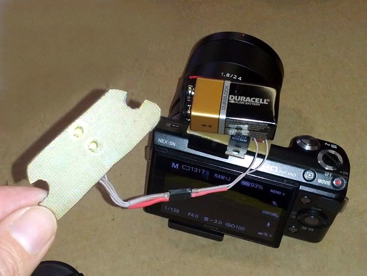
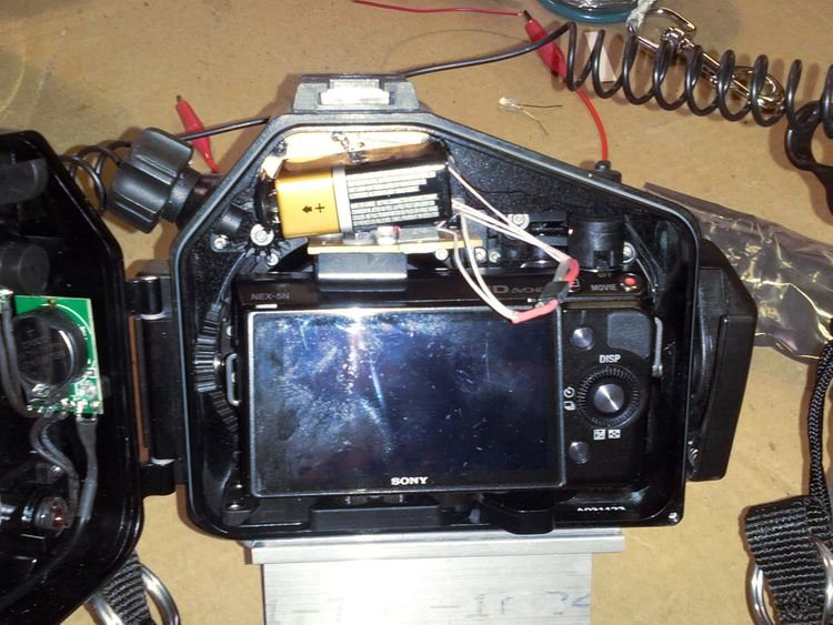
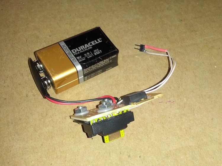
A small circuit board plugs into the accessory port of the camera, and a 9V battery rests on top of it. Two small high-powered LEDs are affixed to the inside of the underwater housing, positioned over the ends of the fiber optic cables. A detachable connector on the wires allows the LEDs to be semi-permanently attached to the inside of the housing, yet also easily disconnected from the circuit board to allow the camera to be removed from the housing.
There are some more detailed photos of the finished circuit board below.
The project took two months and the costs broke down like this:
-
Hot shoe adapter: $25
-
Two high-powered LEDs: $10
-
Generic “IC pattern” proto-board: $3
-
NTE-2987 MOSFET (aka transistor): $4.50
-
9V battery and connector: $3
-
#4 screws from Home depot: $3
-
Teflon-coated wire, IDC connectors, shrink tubing, nylon washers, copper-clad PCB, qty. 2 resistors: scraps from Hackerbot Labs
-
Total: about $50.
…plus expenditure on a few parts that didn’t work:
-
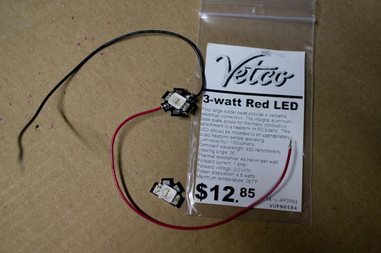
qty. 2 3-watt red LEDs that I fried: $25
-
Small high-lumen LED flashlight that wasn’t bright enough: $10
-
qty. 4 infrared LEDs that weren’t bright enough: $20
-
qty. 2 disposable cameras with flash: $12
Design and build process
Big thanks to 3ric (full disclosure: he was my sig other at the time) for providing tools like the bench power supply and the microscope, as well as general electronics mentoring, and the crucial contribution of finding the pinout diagram for the hot shoe unit.
Light source
First, I needed to find a light source that would trigger my external strobes. It turned out that a lot of light is required to trigger these strobes, particularly through fiber-optic cables, since the cables seem to attenuate the light significantly.
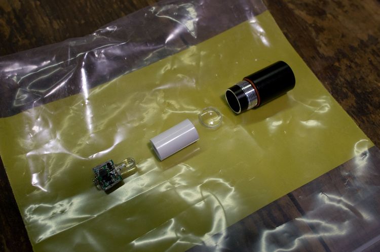
I started out with a standard LED; too dim. Then I tried an LED out of a small high-lumen flashlight. Still not bright enough! I became worried that LEDs just weren’t going to cut it, so I looked into using an actual strobe from a disposable (film) camera. (Yes, they still make those!) I obtained and took apart a disposable camera, and discovered that the circuit board would be a struggle to fit into the underwater case… and besides, exposed circuitry that includes a charged 330V capacitor is not my idea of a safe project. So it was back to LEDs. Next I tried a 3-watt high-powered red LED. This was bright enough, barely, but it came on a backing that was about the size of a penny, which was awkward in the space requirements. What finally worked was this tiny, super-bright LED (about 4 watts) from Sparkfun for only $5. They were small enough that I could use one for each fiber-optic cable, so to be on the safe side I ordered eight. (In the end I wound up using four on the project — two failed due to the lenses breaking off.)
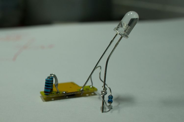
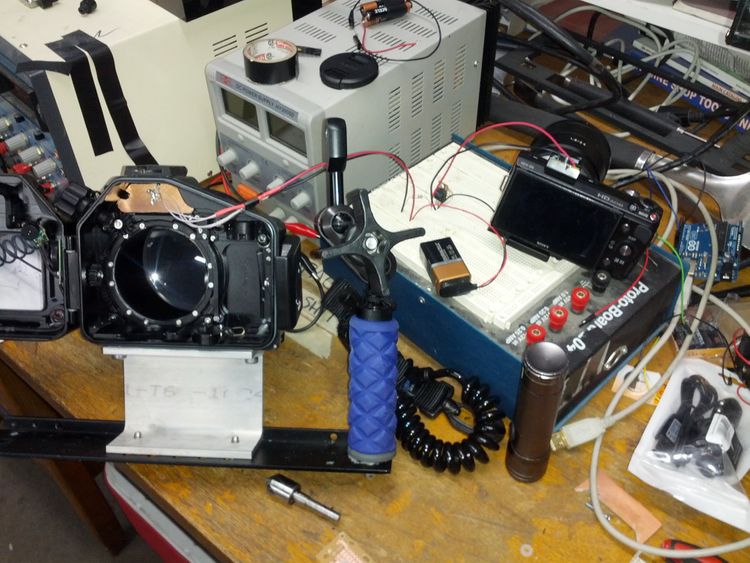
How did I test the LEDs? I used a breadboard to set up a circuit using a bench power supply. I could set the bench supply to the volts and amps appropriate for the LED I was testing, without having to bother with a resistor. Because I only wanted the LED to flash for half a millisecond (to emulate a strobe), I incorporated an N-channel MOSFET into the circuit and signaled the gate of the MOSFET with an Arduino. I programmed the Arduino to send a brief high logic signal whenever it started up, so that I could trigger the LED by pressing the reset button on the Arduino. I generally had to solder wires to the LEDs’ breakout boards to be able to plug them into the breadboard and test them.
Here is a circuit diagram for my test circuit:
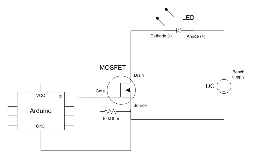
Note that there is a pulldown resistor between gate and source because that seemed to be a best practice recommended in a few places. (I guess I had to dig out a resistor anyway.)
Here’s the program listing for the Arduino. I used port manipulation for more precise signaling due to the short delay times involved. I had the builtin LED turn on along with the logic pin for my circuit, so that I could more easily troubleshoot.
// Pin 13 has an LED connected on most Arduino boards.
int builtin_led = 13;

int led = 12;

// the setup routine runs once when you press reset:
void setup() {
  delay(1000);
  pinMode(led, OUTPUT);
  pinMode(builtin_led, OUTPUT);

  digitalWrite(builtin_led, HIGH);   // turn the LED on

  PORTB = B00010000; // sets digital pin 12 HIGH
//  delay(3000);
  delayMicroseconds(500);
  PORTB = B00000000;

  digitalWrite(builtin_led, LOW);   // turn the LED off
}
Triggering with the camera
Once I had identified LEDs that could trigger the strobes, next up was get the LEDs to flash on signal from the camera. I disassembled the hot shoe adapter for its circuit board, and 3ric helped me figure out how to get it to produce a logic signal when it’s plugged into the camera and the shutter button is pressed.
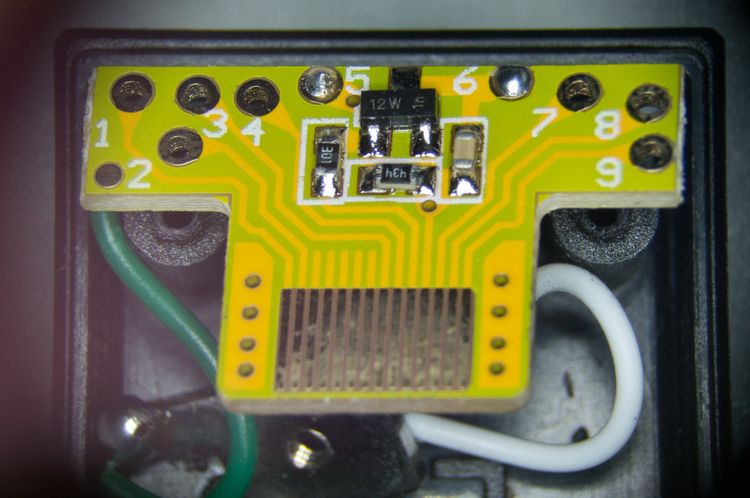
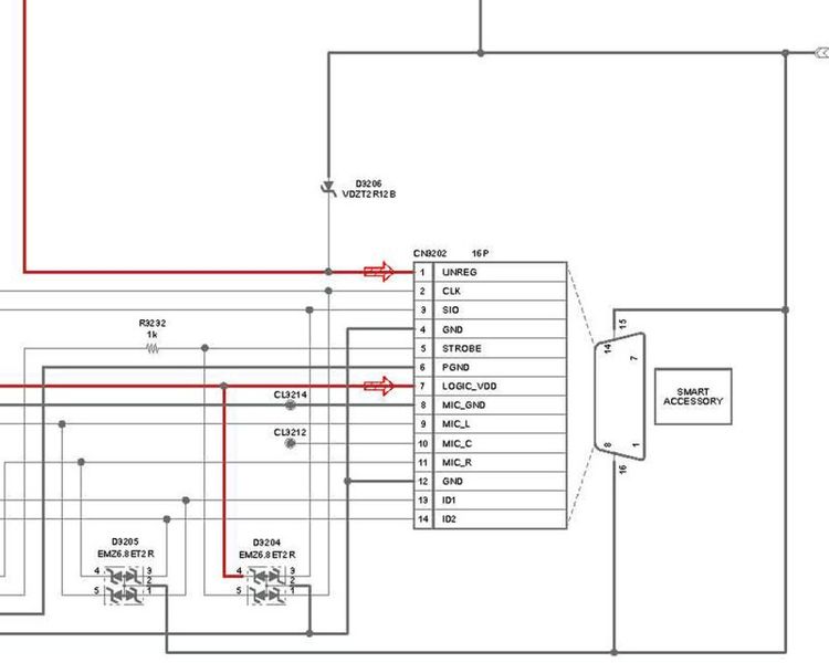
We relied on a pinout diagram (found here) of the “smart connector” that others had posted on forums (apparently made by someone reverse engineering the NEX-5 flash unit). Knowing from this diagram what each contact meant, we could trace it to the corresponding through-hole. The hard part was figuring out the fact that the camera wanted signal on the two ID pins in order to cooperate. As you can see in the photo below, we simply slapped on a couple of 10 kOhm resistors at pins 1 and 2, and connected them to the ground on pin 4. This made the camera happy enough to send the strobe signal. To test, we soldered in an LED and current-limiting resistor. The LED worked when wired between pins 9 and 6; pin 6 does the switching. (There appears to be a little circuit on-board that produces switched ground at pin 6 based on the signal from pin 5, which is presumably the pin the camera uses to tell the hot shoe to trigger the flash.)
At this point I could solder some leads into the hot shoe circuit board at pins 9 and 6, plug the board into the camera, and simply swap it out for the arduino in the breadboard test circuit. It turned out the timing of the logic signal coming from the camera (about 100 milliseconds duration) was perfectly adequate to trigger the MOSFET. I was also fortunate that the mere ~1 volt of signal coming from the hot shoe circuit board was sufficient to saturate the MOSFET’s gate. (The voltage and duration of the camera signal were found by analyzing it with an oscilloscope; thanks to Rich for help with this.)
Finalizing the circuit
It was now time to exchange the bench supply for a battery, and finalize the details of the circuit.
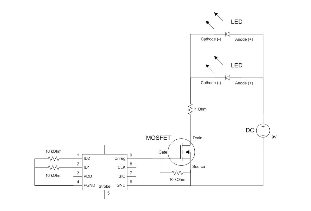
Below is the circuit diagram. I wanted to run two LEDs in parallel, at the max forward voltage of 4V and a forward current of 2.5A. (This is overdriving the LEDs to get more brightness out of them: the max forward current in the datasheet is 1A.) I decided to go with a 9V battery since I would have had to stack many coin cells to get enough volts, and I would have had to replace them more frequently; plus it seemed like I could fit a 9V in the space available. It turned out to be so snug that I didn’t even need a holder for the battery!
Ignoring the small forward voltage on the MOSFET, these constraints set up the resistor to have 5V of drop and 5A of current. V = IR so R = V/I = 5/5 = 1 ohm is the current limiting resistor I chose.
One important detail is power (heat) dissipation. When a component like an LED or a resistor is operated continuously, it can generate a lot of heat that can burn out the component if not handled. For a resistor, you need to pay attention to the rating; most resistors are only rated for a couple hundred milliwatts, but for my application I technically needed at least a 2W rated resistor (probably more like 25W). However, it turned out that by only ever flashing the LEDs for very short intervals, heat accumulation was not a problem. So I could get away without dealing with it basically. The short duration was probably also protective for the LEDs, even though I was overdriving them, but in the end I mounted them to a metal coated board which may have acted like a heat sink. Anyway, I never had any of these components fail.
Installing the LEDs into the housing
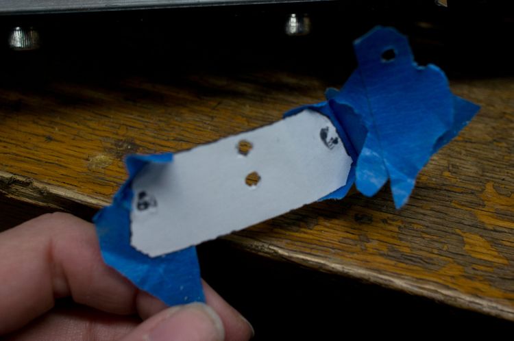
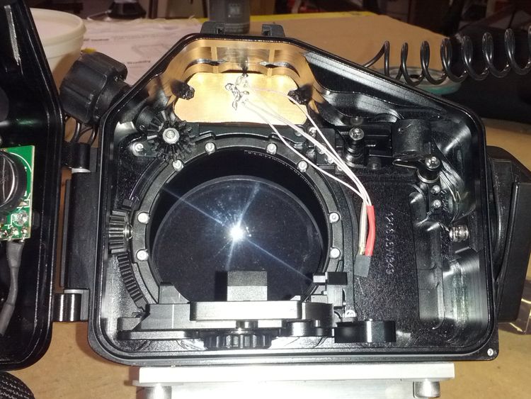
The housing has a transparent bulkhead in front of where the camera’s built-in flash is supposed to be located. There is a cover installed over the bulkhead with small holes in it, which the ends of the fiber optic cables just fit into, and are held in place by friction. So the LEDs inside the housing needed to be lined up with the ends of those tiny fiber optic cables, in order to get enough light into them to trigger the slave strobes. To achieve this, I followed 3ric’s excellent suggestion of making a template.
I cut a piece of paper to just fit the shape of the transparent bulkhead on the inside of the housing, and then shined a bright flashlight through the fiber optic cable holes on the outside of the case. This allowed me to mark the spots on the paper that were just aligned with the ends of the fiber optic cables. Then, I traced the shape of the paper template onto a scrap piece of one-sided copper-clad board, and trimmed it to shape with a Dremel fitted with a cutting wheel. Finally, I taped the template to the CCB and used the holes I had marked as guides for drilling. A lesson I learned: Use a center punch to ensure that the hole ends up exactly aligned with the mark, because without a dent to guide the drill bit to center, the bit has a tendency to wander when starting the hole. And practice with the center punch on a piece of scrap because if you hit it too hard, you can shatter the board.
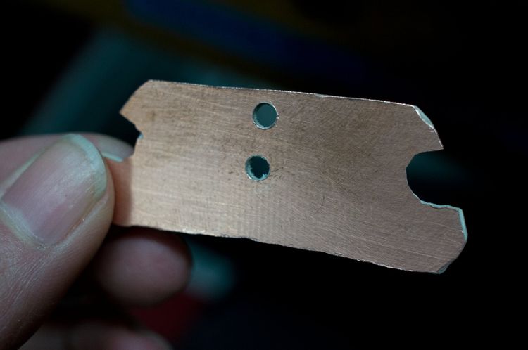
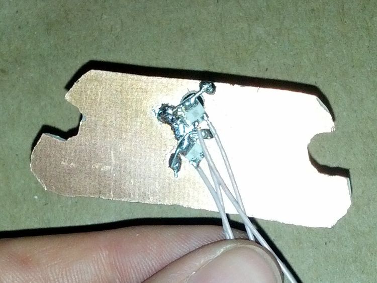
Next, I soldered the LEDs onto the board. I arranged the board so the copper side faced away from the bulkhead, so I could solder to it. The LEDs were positioned face down, so that the lenses of the LEDs nestled into the holes. In the photo below, the top hole is larger because I had to migrate the hole downward a bit to improve alignment. To attach the LEDs to the board, I used two small pieces of solid wire as a bridge, and I soldered the wire to each LED’s heat sink attachment point and to the CCB on either side. This was tricky work because whenever my soldering iron heated the wire up, the wire had a tendency to come loose from its other attachment points. A little patience and I got them on.
I finished the ends of the wires with an IDC connector. This is a small plastic connector that has a pin on one side and a socket on the other side. It comes in a long strip that you can cut to size; I used two adjacent segments for + and -, and I finished the wire joints with color coded shrink tubing to ensure that I could connect them together the right way.
Finally, after testing that the positioning was right, I used two small pieces of museum putty to attach the plate to the bulkhead. This was sticky enough to keep it firmly in place, but forgiving enough that I could remove the plate by prying with the tip of a flat bladed screwdriver.
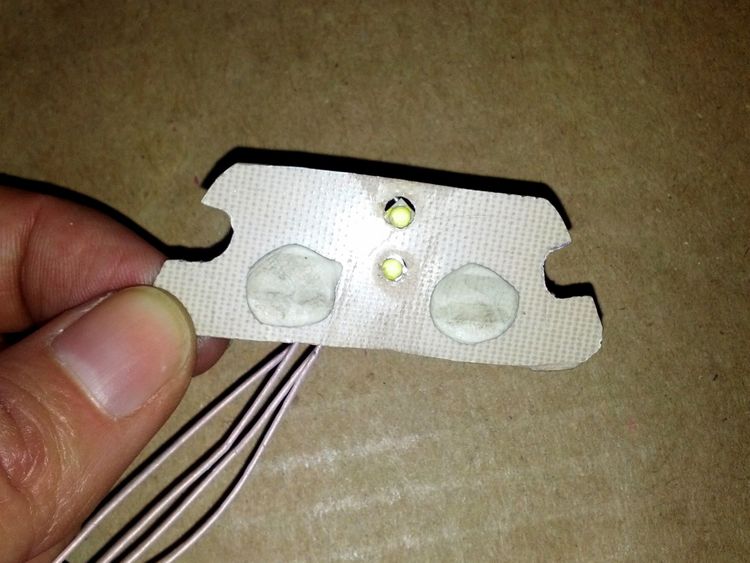
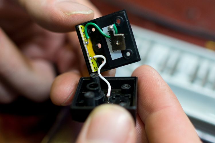
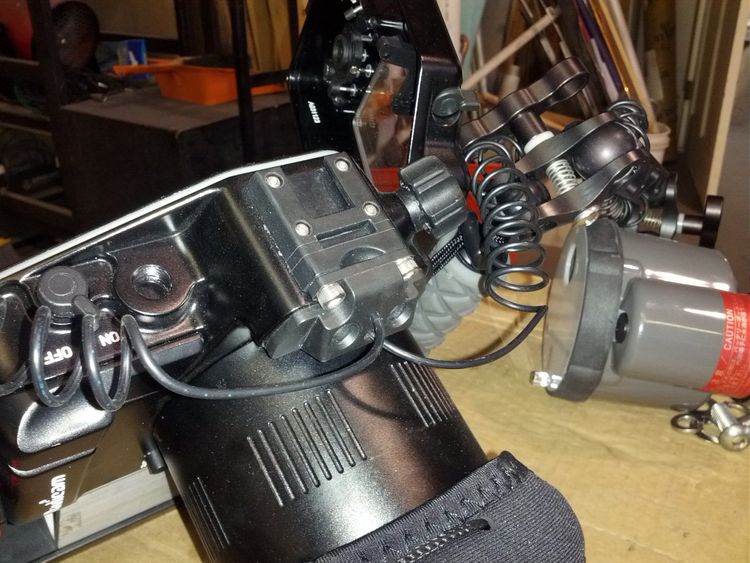
For finishing touches, I added a dab of hot glue as strain relief, and covered the electronics with Kapton tape. The photo below shows the finished plate installed in the housing. This shows the red shrink tubing on the positive lead only, to avoid connecting it backwards.
Crafting the hot shoe module and circuit board
For the final module, I decided to use the bottom part of the hot shoe case, and attach the circuit board to the top of it. This required two tries to get right. Below is my second and more successful attempt.
Here’s how things looked during the fitting process. You can see that the ID pin resistors just barely make it into the space available in the hot shoe case.
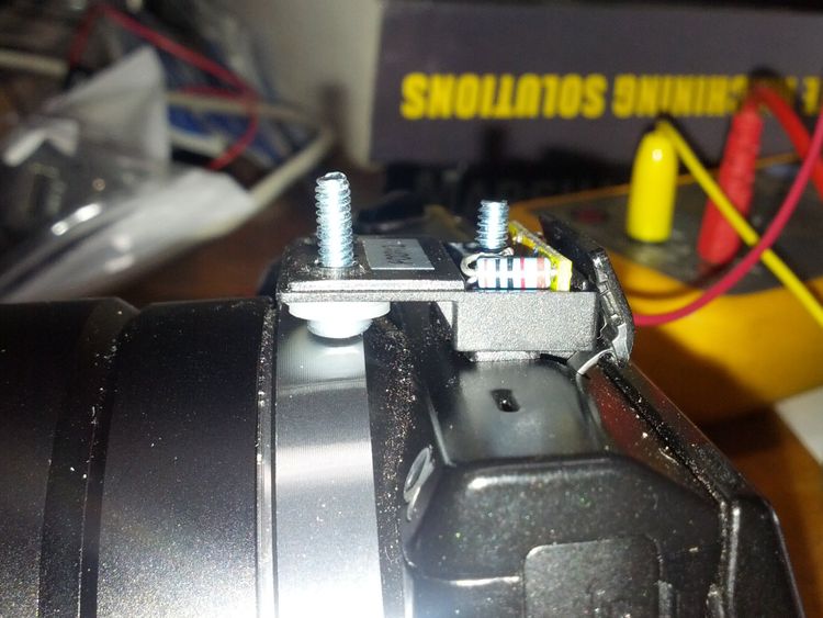
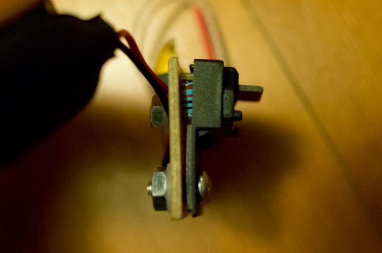
Here’s the side view, after attaching the circuit board.
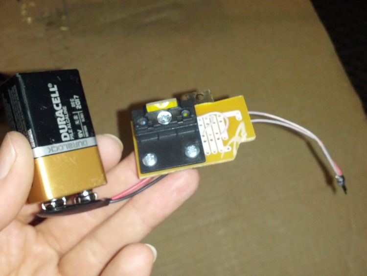
On the bottom view, you can see that I reused existing holes from the hot shoe case screws, though I had to drill them a little larger. For the rear center fastener, I had to use a flat head screw and countersink the hole quite a bit to get the screw head flush, which was necessary in order to fully seat the accessory contacts in the camera slot. For the two other screws, I used round heads that wound up adding just enough spacing so that the front of the unit could rest on the camera (as seen in Fig. 19).
For the circuit board, I used ready-made protoboard which I Dremeled to size. Laying it out involved a process of narrowing down the placement of physical supports (the screws) and the electronic components by working through all the constraints.
After it was assembled and tested, I added strain relief on the wires. I tied down the LED wires with another, bare wire through two circuit board holes, and I routed the battery wires under the nylon washer of the rear screw post. And I added a strip of Kapton tape here too (it turned out that the case of the battery was shorting against the MOSFET heat sink and causing the strobes to fire unpredictably, and the tape took care of that).
Yes, I know that I put the components on the board upside-down. I was informed of this after I built it. Works just fine, apparently it’s just easier to solder if the pin is sticking out of the hole and the component is underneath the board.
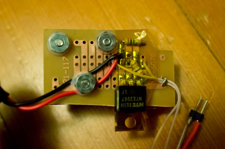
On the back view of the finished module, note that the hot shoe circuit board and the main circuit board touch each other. This allows the unit to be firmly seated in the camera’s accessory port by pressing down on the main board.
Results
I took the whole setup out for the first time on Saturday, 2/9/13 and it performed great! The sample photo at beginning of the post was taken on that maiden voyage.
One thing I learned was that making a custom component, especially as an amateur, involves reliability risk. At one point when I was in Indonesia, one of the solder joints failed, and of course I had no tools to fix it … but I could have easily brought along a spare unit, if I had made one. (Or, I guess, I could have brought the OEM strobe unit as a backup, LOL.) The point is that in DIY, the time investment of figuring it out the first time seems like the heaviest lift on the project. So, once the feasibility question is settled, why not make several units while you’re at it?